In the summer of 2013 I bought two Acoustic 371 systems, hoping to get at least one complete working system out of all the parts. The first restoration project went so well that I’ve now started a restoration on the other system. I will keep one 371 and sell the other one (maybe). The history, restoration write up, owner’s manual, schematics, photos, parts invoices, ads from old guitar magazines, product brochures, etc. will be included in a 3 ring binder.
So here is the 301 that just arrived from Huntsville, Alabama, USA. I didn’t know what to expect but the shipper left the casters and handles exposed so that UPS could just roll it on and off the truck. General condition is decent and the woofer, a Cerwin Vega AC188 L is in great shape. (My first 371 restoration can be seen on the left. I plug into that baby every weekend and cause ever widening cracks in the house’s foundation).


The underside of the cabinet is a mess as is typical for this design (the old rusty casters are gone, replaced by the new ones). The corners are mashed and rusted. Acoustic used corners that are more appropriate for jewelry boxes, not 150 pound speaker cabinets. They will be replaced by much stronger hardware.
These seriously rusted corners have seen their share of rainy load-ins and gigs. And here are the equally nice connections for delivering high current bass power to the woofer. These connections rate right up there as some of the coldest solder joints I’ve ever seen. When I was a 12 year old kid and first started to use a soldering iron, I’m sure mine looked like this too. Anyway, with all that resistance, I’ll bet these connections got quite hot during long musical performances.


And speaking of resistance:
DAMPING FACTOR (DF) is one of the most critical performance specifications in the world when it comes to bass amplifiers, big woofers and speaker cable/connectors. So listen up: The woofer’s cone is supported in the speaker frame by two springs, namely the Surround (at the front edge of the cone) and the Spider (at the back of the cone, next to the magnet). If a theoritical instaneous pulse of power is sent to the speaker, it would create an electomagnetic field in the voice coil. And since the coil is submerged inside the gap of the speaker’s permanent magnet, these magnetic fields suddenly oppose each other, forcing the coil and cone to move out of the gap for that instant.
The original power pulse has passed but the cone’s “springs” now pull it back towards it’s rest position. Unfortunately, due to the law of inertia, the cone doesn’t stop at it’s rest point, it continues moving through this point and when it reaches the opposite excursion limit, it reverses direction and then again heads back towards it’s rest position. This residual back and forth movement eventually settles down and the cone comes to rest. So far, the pulse was turned into cone movement by opposing magnetic forces. This resulted in generating an acoustic wave that eminates outward towards your ears and the rest of the world. All the residual back and forth movement was also turned into acoustic waves but they are just unrelated (bad sounding) artifacts. All these unrelated cone movements result in the voice coil generating a signal that actually heads back towards the amps’s output stage. This is called Back-ElectroMotive-Force (Back EMF).
Amplifier circuit design engineers can stop these back and forth movements by designing the amp’s output stage to have very low internal resistance/impedance characteristics, most notably by the use of negative feedback. The expression that relates to this capability is referred to as Damping Factor. The lower the output stage resistance, the higher this performance number becomes. The higher the number, the better the amp is at being able to push back against the Back EMF signal/residual cone movement. It is literally able to stop the speaker from flopping around after the original “pulse” is gone. Electrically, it is short circuiting the voice coil. A full description is not practical here but I did want to bring the subject back to wire size and connector quality. Thin wires, long length and poor connections are a recipe for high resistance (see photo below) which will destroy the amp’s DF performance and will result in muddy sounding bass notes. You and I should never want to hear our guitars sounding like mud. The lessons here are to use the thickest wire possible, keep the length of the speaker wire as short as practical and make sure your connections are clean and tight. The lower the resistance in the path between the amp and the woofer, the better the amp will be able to damp out these extraneous, muddy artifacts. Amen.
If you would like to prove it to yourself, press on the cone of a woofer that is completely disconnected from an amp. Feel the springiness? Now take a piece of wire or a heavy duty clip lead and short the speaker terminals together. Now try pushing on the cone. Amazingly, it will resist your efforts. Pretty cool.
The cable holders on back panel of the 370 bass amp head have been ripped out a couple of times. And this piece of the power cord was on the inside of the chassis. There’s lots of opportunity for a cleanup in there. Strangely, when I first plugged in the amp, it powered up without turning on the switch. I found that the power switch had been bypassed for some reason unknown. The switch (7A) worked but I replaced it with a higher rated switch (10A) because I’ve heard that the original switches sometimes fail, presumably due to high in-rush currents that exceed the contact ratings.


The front panel is really scratched up, which is a total bummer (this is where my wife’s help will come in handy). In these photos, I replaced the volume and tone control knobs, the neon power light, put in a 15′ flexible grounded power cord, removed the death capacitor, cleaned the entire chassis, circuit boards, capacitors, connections and resoldered the bridge rectifier. It’s solder joints looked like the ones on the woofer. I swear that one wire was being held in place only by some dried flux. Note that this is not the original big, green bridge rectifier that Acoustic used in many power supplies. From the three Acoustic amps that I’ve worked on, all the originals failed for one reason or another. The new ones have double the PIV, 400 volts.


After all the hardware is removed, the old ratty, smelly Tolex is ripped off the 301. Fortunately, it peels off easily. The most difficult item to get off the cabinet is the serial number plate. I used stiff putty knives, adding one after the other until the “twist nail” head was out enough to grab it with a pair of Vice Grip pliers. This process takes a lot of patience to avoid bending the plate. One of the forum regulars suggested that heating the wood and plate with a heat gun makes it easy to remove. Guess I’ll have to try that next time around.


I take a break while my supervisor Jasmine checks on progress so far. And take a look at this smiley face, painted by some bored Acoustic factory worker way back in 1974. If you look to the left of this image, you will see three strips of tape being used to hold a sliver of plywood that is being glued back into the edge. In it’s present condition, this cabinet has many splinters just waiting to jab you and then break off under your skin somewhere. I’ve learned to never run my hand over the wood surface carelessly.


I’m using a power sander connected to my shop vac to keep the dust down. Ear plugs are mandatory. In the next photo, the speaker grills get a good scrubbing with soapy water.


After rinsing, bricks are used to keep the plywood frames from warping. This works well. I fabricated a pair of aluminum “modesty” plates to cover all the messed up screw holes in the back panel of the amp. Everything got painted and nuts and bolts were used to hold the cable holders in place, instead of sheet metal screws. You’ll see the finished product a little later in this thread.


I removed the handles from all my Acoustic equipment, spent and entire weekend removing the old paint and corosion. Then on a nice, warm, sunny day, I took them outside and hit them with spray paint. They came out beautiful if I don’t say so myself. These two photos also appear in my other restoration thread but it’s worth noting here because three of the handles belong to this system.


All the parts for the 301 Transducer, nicely layed out and ready for hours and hours of hard labor. All the speaker grill fasteners were brittle and thanks to Michael Winter (on this forum) for pointing me to a Corvette America website where I could buy new ones. I’m using pan head wood screws instead of staples so I’ll have to mill out a little recess for the screw heads (the originals had this recess as you can see).


The 370 cabinet gets all sanded down.


All the white stuff is Bondo, used to filling all the dings and undulations in the wood grain. It’s been sanded down to an ultra smooth finish. And now for some TruGlu and Tolex. I painted every surface that wasn’t going to be covered by Tolex with black paint. Nobody will see it but I can’t resist making it as nice as possible for myself or whomever I sell it to down the road. What I’ve noticed about this particular 371 system (1974) is that the factory’s cabinet craftsmanship is just a tiny bit better than the other 371 (1972) I restored last year. They took a little more care when routing out openings for handles, better glue, staples and all around carpentry.


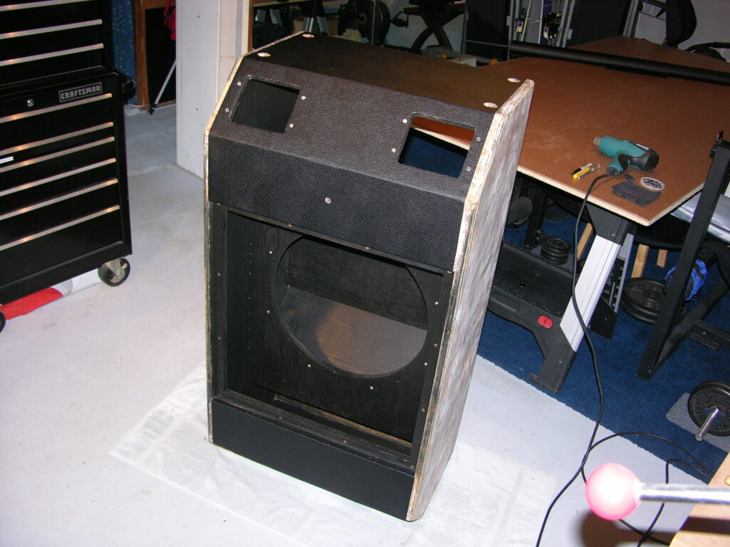
This is the 301 waveguide/back panel. “Waveguide”, what a cool name for a wedge of wood. Typically this term is used in RF engineering for microwaves, not for fifty foot long acoustic waves. But hey, that’s what the factory called it and I’m sticking with it. It is going to be painted black and I’ll have to come up with a more subtle arrow to indicate “Up”. Finally, here are two completed pieces that can now be put aside. I finally feel like I’m making headway.


Made up the speaker cable harnesses with 12 gage Monster Cable. Nothing special about the brand, I just happen to have a big roll so I might as well use it. Since there are two spade lugs on each speaker terminal, I split the wire so I could attach to both pair of lugs for the lowest resistance connections possible. I resisted replacing the lugs with huge binding posts because I’m just trying to keep it as close to original as practical. With regards to the above mentioned topic of damping factor, if I was using new components and didn’t care to remain original, I’d use even heavier gage wire, Neutrik Speakon Connectors (on the amp and speaker cabinet back panel), gold plated binding posts on the woofer and gold plated spade lugs on the internal speaker cabinet wire.

Every facet of the 301 has been sanded down, then Bondo was applied, and sanded down again. Very labor intensive, dusty and not much fun. The surfaces might look “streaked” but close your eyes and run a hand over any surface. It’s as smooth as glass and there are no splinters. Then every corner of the interior was painted with black satin latex. It’s like a black hole in there, this waveguide just soaks up all the light rays. And it looks gorgeous.

Ahhh, Mojotone TruGlu, it’s great stuff. Goes on with a paint brush, splatters like skim milk and washes up with warm water. Apply to both surfaces, let dry until slightly tacky and then press them together. These top and bottom pieces aren’t easy to align properly but fortunately, you can peel up the Tolex and put it back down until you get it right. Then use a roller to press down the large surfaces. Knead all the edges with your thumbs, fingers and palms until no bubbles remain. It takes quite a bit of time. Finally, use a very sharp Exacto Knife to cut out all the bolt, foot cup and handle holes.

Massive progress this weekend. The top and bottom Tolex panels (above) were done yesterday by myself. Today I needed help with the sides since they need two people to lay the Tolex down correctly. A HUGE shoutout to my friend Phil who basically put his day on hold to help me out. I’m sure he came for the pizza and the chance to groove on my GGi4 bass guitar (playing through my other 371 of course!). Anyhow, before gluing, I prepped the pieces with blue tape registration marks so we got the stuff down exactly right the first time. Wrapping the 45˚ edges are tedious and complicated, especially if you want to get them just right. So I’m going to leave them flapping in the breeze for now and dedicate an entire afternoon to get them just right. It’s worth noting that I’ve kept every single facet of Tolex oriented in the same direction as there is a subtle “checkerboard” pattern in it that can sometimes be seen in the right light.
On 3/28 I finished all the corners with the Tolex flaps, bolted on the wheels and the new kick plate. I’ll install Teflon glides on the bottom instead of the single rubber bumper that the factory provided.


Here the T-molding goes in. Heating the corners makes them nice and sharp. Finally, there she stands, ready for the wiring, woofer and grill covers.


Ok, the stack is ready for for electronics. A shout out to my wife Kathy for the bass clef artwork. Yea, it’s hidden behind the woofer so it will never be seen. Except by everyone on the Unofficial Acoustic forum!


AC188 L woofer gets a new dust cap with it’s namesake Cerwin Vega, design courtesy of Gene Czerwinski and Vega Associates. The felt surround is hit with a little black spray paint to give it a new look. The woofer is in fine condition but this work is intended to improve the visual appeal for my own gratification (or a future sale?).

Now to test the woofer with my other 370 (restored last year) and GGi4 bass before it gets bolted in. Then Mortite calking goes down to seal the woofer to the baffle. This is nice stuff to work with because it stays pliable for years.


Woofer installed with new, heavy duty aluminum clamps, back waveguide panel bolted down and serial number plate screwed in. The 301 is done!


Over the past couple of weeks of April/May, I’ve been trying to decide how best to make the 370 amp head look new. There was a lot of wear and tear to all the painted surfaces. I couldn’t take it down to bare metal because of the graphics. So, hand paint it? Nope, we tried it in a couple of areas and it didn’t look too good. Ok, spray paint it? Well, after much bitching to myself about how labor intensive the masking was going to be, I got down to work. Everything, down to the pan head bolts got masked off with painters tape. It’s taking forever. All the bolts on the bottom of the amp had lost their shine so I replaced them all. Guess I could have buffed them all….

Everything that could come off, came off. Everything that was connected by wires was wrapped with tape. All surfaces were lightly sanded and wiped down with mineral spirits and then hit with black satin from a rattle can. Each surface took a weekend to do and then it had to wait till the next weekend. You’re looking at a month’s worth of work, so far. Protecting the volume and tone control graphics was a story all it’s own because it had to be perfect. Long story short, I found four perfectly round plastic caps, drilled out their centers and taped them on to the control knobs. Came out very nice. Relief….

Here’s the paint and other weapons used for touching up the silkscreen details. And of course here’s the artist herself (Kathy, my wife) using a sharp eye and a steady hand. She used Testors model paint and getting the right “Acoustic powder blue” took three colors mixed just right (blue, green and white).

Finally, the 370 Bass Amplifier makes an appearance in finished condition. It’s far from perfect but it’s ten times better than what I started with. BTW, it might be hard to see but the previously mentioned “modesty plates” are now covering all the screw holes behind the cable holders. And of course the cabinet has been refinished with new Tolex, all new corners, nylon feet, bolts and screws.


Presenting the full stack: The Acoustic Control Corporation 371 Bass System


For each restoration project, I assemble a 3 ring binder with everything needed to take this system into the future. It includes an introduction to ACC’s 371 with lots of historical details and quotes from Russ Allee and Harvey Gerst. It also includes the owners manual, service manual, schematics, restoration story, my purchase info, repair parts invoices, magazine ads and reviews. In the image below, from left to right, it’s the 3 ring binder, an original ad for the 371 out of a Guitar Player magazine and a photo of Harvey Gerst and Russ Allee. Side note: Kathy helped me create a title page using Photoshop (the photo is of my first 371). Each section is headed up with this page along with the title of the particular section (aka, “Schematics”, Owners Manual”, etc.).


Materials used for this restoration project:
Tolex, Tru-Glue, chrome corners: Mojotone.com
Speaker dust cap with logo for AC-188 L: SoundSpeakerRepair.com (ask for Rich)
Bolts, black oxide (of which there were many) – BMBfasteners.com
Speaker clamps, black, metal: Usspeaker.com (stock #: G0790)
Casters: Grainger.com (item #: 4X696, Rigid Plate Caster, 176 lb., 3″ diameter)
Aluminum kick plate: Onlinemetals.com (stock #: 5052 or 6061)
White T-molding: T-molding.com (stock #: T-WHT-81)
Foot cups, black plastic: Pirk (search this forum)
370 volume and tone control knobs: Newark.com (SKU #: 29C0178, Mfgr Pn. PC1F2B)
Mortite caulking cord for sealing the speaker and rear waveguide panel: Frostking.com
And so we’ve come to the end of my second and final 371 restoration project. In my opinion, the 371 is the greatest sounding, most awesome looking bass amp that Acoustic ever made. There will never be another amp like this and I’ve done everything within my power and abilities to preserve it’s legacy. Thank you for following along, it’s been a long and rewarding road since I began these two projects in the summer of 2013.